
Example FortiGate PIM-SM configuration using a static RP
The example Protocol Independent Multicast Sparse Mode (PIM-SM) configuration shown below has been tested for multicast interoperability using PIM-SM between Cisco 3750 switches running 12.2 and a FortiGate-800 running FortiOS v3.0 MR5 patch 1. In this configuration, the receiver receives the multicast stream when it joins the group 233.254.200.1.
Example FortiGate PIM-SM topology
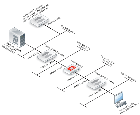
The configuration uses a statically configured rendezvous point (RP) which resides on the Cisco_3750_1. Using a bootstrap router (BSR) was not tested in this example. See “Example PIM configuration that uses BSR to find the RP” for an example that uses a BSR.
Configuration steps
The following procedures show how to configure the multicast configuration settings for the devices in the example configuration.
- Cisco_3750_1 router configuration
- Cisco_3750_2 router configuration
- To configure the FortiGate-800 unit
- Cisco_3750_3 router configuration
Cisco_3750_1 router configuration
version 12.2
!
hostname Cisco-3750-1
!
switch 1 provision ws-c3750-24ts
ip subnet-zero
ip routing
!
ip multicast-routing distributed
!
spanning-tree mode pvst
no spanning-tree optimize bpdu transmission
spanning-tree extend system-id
!
interface Loopback0
ip address 169.254.100.1 255.255.255.255
!
interface FastEthernet1/0/23
switchport access vlan 182
switchport mode access
!
interface FastEthernet1/0/24
switchport access vlan 172
switchport mode access
!
interface Vlan172
ip address 10.31.138.1 255.255.255.0
ip pim sparse-mode
ip igmp query-interval 125
ip mroute-cache distributed
!
interface Vlan182
ip address 169.254.82.250 255.255.255.0
ip pim sparse-mode
ip mroute-cache distributed
!
ip classless
ip route 0.0.0.0 0.0.0.0 169.254.82.1
ip http server
ip pim rp-address 169.254.100.1 Source-RP
!
ip access-list standard Source-RP
permit 233.254.200.0 0.0.0.255
Cisco_3750_2 router configuration
version 12.2
!
hostname Cisco-3750-2
!
switch 1 provision ws-c3750-24ts
ip subnet-zero
ip routing
!
ip multicast-routing distributed
!
spanning-tree mode pvst
no spanning-tree optimize bpdu transmission
spanning-tree extend system-id
!
interface FastEthernet1/0/23
switchport access vlan 138
switchport mode access
!
interface FastEthernet1/0/24
switchport access vlan 182
witchport mode access
!
interface Vlan138
ip address 10.31.138.250 255.255.255.0
ip pim sparse-mode
ip mroute-cache distributed
!
interface Vlan182
ip address 169.254.82.1 255.255.255.0
ip pim sparse-mode
ip mroute-cache distributed
!
ip classless
ip route 0.0.0.0 0.0.0.0 10.31.138.253
ip route 169.254.100.1 255.255.255.255 169.254.82.250
ip http server
ip pim rp-address 169.254.100.1 Source-RP
!
!
ip access-list standard Source-RP
permit 233.254.200.0 0.0.0.255
To configure the FortiGate-800 unit
- Configure the internal and external interfaces.
- Internal
Go to System > Network > Interfaces.
Select the internal interface.
Verify the following settings:
| Type: | Physical Interface |
| Addressing mode: | Manual |
| IP/Network Mask: | 10.31.138.253 255.255.255.0 |
| Administrative Access: | PING |
Select OK.
- External
Go to System > Network > Interfaces.
Select the external interface.
Verify the following settings:
| Type: | Physical Interface |
| Addressing mode: | Manual |
| IP/Network Mask: | 10.31.130.253 255.255.255.0 |
| Administrative Access: | HTTPS and PING |
Select OK.
- Add a firewall addresses.
Go to Policy & Objects> Objects > Addresses.
- RP
Select Create New.
Use the following settings:
| Category: | Address |
| Name: | RP |
| Type: | Subnet |
| Subnet/IP Range: | 169.254.100.1/32 |
| Interface: | Any |
| Visibility: | <enabled> |
Select OK.
- Multicast source subnet
Select Create New.
Use the following settings:
| Category: | Address |
| Name: | multicast_source_subnet |
| Type: | Subnet |
| Subnet/IP Range: | 169.254.82.0/24 |
| Interface: | Any |
| Visibility: | <enabled> |
Select OK.
- Add destination multicast address
Go to Policy & Objects> Objects > Addresses.
Select Create New.
Use the following settings:
| Category: | Multicast Address |
| Name: | Multicast_stream |
| Type: | Broadcast Subnet |
| Broadcast Subnet: | 233.254.200.0/24 |
| Interface: | Any |
| Visibility: | <enabled> |
Select OK.
- Add standard security policies to allow traffic to reach the RP.
Go to Policy & Objects > Policy > IPv4.
- 1st policy
Select Create New
Use the following settings:
| Incoming Interface: | internal |
| Source Address: | all |
| Outgoing Interface: | external |
| Destination Address: | RP |
| Schedule: | always |
| Service: | ALL |
| Action: | ACCEPT |
Select OK.
- 2nd policy
Select Create New
Use the following settings:
| Incoming Interface: | external |
| Source Address: | RP |
| Outgoing Interface: | internal |
| Destination Address: | all |
| Schedule: | always |
| Service: | ALL |
| Action: | ACCEPT |
Select OK.
- Add the multicast security policy.
Go to Policy & Objects > Policy > Multicast.
Select Create New.
Use the following settings:
| Incoming Interface: | external |
| Source Address: | multicast_source_subnet |
| Outgoing Interface: | internal |
| Destination Address: | multicast_stream |
| Protocol: | Any |
| Action: | ACCEPT |
Select OK.
- Add an access list. (CLI only)
config router access-list
edit Source-RP
config rule
edit 1
set prefix 233.254.200.0 255.255.255.0
set exact-match disable
next
end
- Add some static routes.
Go to Router > Static > Static Routes.
- Route 1
Select Create New.
Use the following settings:
| Destination IP/Mask: | 0.0.0.0/0.0.0.0 |
| Device: | internal |
| Gateway: | 10.31.130.250 |
| Distance: | <default> |
| Priority: | <default> |
Select OK.
- Route 2
Select Create New.
Use the following settings:
| Destination IP/Mask: | 169.254.0.0/16 |
| Device: | external |
| Gateway: | 10.31.138.250 |
| Distance: | <default> |
| Priority: | <default> |
Select OK.
- Configure multicast routing.
Go to Router > Dynamic > Multicast.
Add the following Static Rendezvous Point(s):
• 169.254.100.1
- Route 1
Select Create New.
Use the following settings:
| Interface: | internal |
| PIM Mode: | Sparse Mode |
| DR Priority: | <not needed in this scenario> |
| RP Candidate: | <not needed in this scenario> |
| RP Candidate Priority: | <not needed in this scenario> |
Select OK.
- Route 2
Select Create New.
Use the following settings:
| Interface: | external |
| PIM Mode: | Sparse Mode |
| DR Priority: | |
| RP Candidate: | |
| RP Candidate Priority: |
Select OK.
Cisco_3750_3 router configuration
version 12.2
!
hostname Cisco-3750-3
!
switch 1 provision ws-c3750-24ts
ip subnet-zero
ip routing
!
ip multicast-routing distributed
!
spanning-tree mode pvst
no spanning-tree optimize bpdu transmission
spanning-tree extend system-id
!
interface FastEthernet1/0/23
switchport access vlan 128
switchport mode access
!
interface FastEthernet1/0/24
switchport access vlan 130
switchport mode access
!
interface Vlan128
ip address 10.31.128.130 255.255.255.252
ip pim sparse-mode
ip mroute-cache distributed
!
interface Vlan130
ip address 10.31.130.250 255.255.255.0
ip pim sparse-mode
ip mroute-cache distributed
!
ip classless
ip route 0.0.0.0 0.0.0.0 10.31.130.1
ip http server
ip pim rp-address 169.254.100.1 Source-RP
!
!
ip access-list standard Source-RP
permit 233.254.200.0 0.0.0.255
Copyright © 2018 Fortinet, Inc. All Rights Reserved. | Terms of Service | Privacy Policy
